

Why Counterweights Matter in Crane Stability and Load Capacity
When operating cranes on Australian construction or infrastructure projects, several factors influence lifting capacity and overall stability, one of the most critical being the counterweight system. Whether you’re an operator managing a 100-ton crawler crane or a project manager hiring an all-terrain model, understanding how counterweights work is essential for ensuring safety, compliance, and lifting efficiency.
Counterweights are not just metal or concrete slabs, they’re the engineering backbone that stabilizes lifting operations, prevents tipping, and enables cranes to reach their full capacity. This article explains how counterweights contribute to crane stability and load capacity, using real-world data and standards aligned with AS 2550.1 and AS 1418.5.
What Are Counterweights in Cranes?
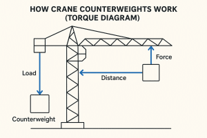
A counterweight is a mass attached to the crane’s superstructure to balance the force generated by the load being lifted. In principle, the crane acts as a lever: the load on one side creates torque, which the counterweight offsets on the opposite side.
Crane counterweights can be:
- Fixed (as in tower cranes)
- Modular (as in mobile and crawler cranes)
- Hydraulically variable (in Superlift systems)
Proper configuration of these weights is what makes high-capacity, long-reach lifting possible.
How Counterweights Maintain Crane Stability
Cranes are susceptible to tipping if the center of gravity (CoG) shifts outside their base support area (defined by outriggers or track width). Counterweights keep the CoG within safe limits, even as the boom swings or radius increases.
Without the correct counterweight:
- A crane becomes unstable during boom extension.
- Swing operations may cause rotational overload.
- Outriggers or tracks may lift, leading to collapse.
The Physics of Crane Stability
Cranes function as rotating levers, where the load creates a moment (torque) around the pivot point (slewing ring or chassis center), and the counterweight provides an opposing moment to balance it.
Basic Moment Equation
Moment = Force × Distance
Where:
- Force = Load weight (in kilonewtons or tons)
- Distance = Horizontal distance (radius) from pivot point
- Moment (Nm or tons-meters) = Rotational force acting on the base
Below is visual representation
Stability Principle
A crane is in equilibrium when:
(Load Weight × Load Radius) ≤ (Counterweight × Counterweight Radius)
If this condition is not met:
- The crane rotates toward the load
- The tipping point is exceeded
- Outriggers may lift, tracks may shift, and full structural collapse can follow
How Counterweights Enhance Load Capacity
Counterweights allow cranes to lift more weight at greater distances. For example, based on an actual load chart for an all-terrain crane:
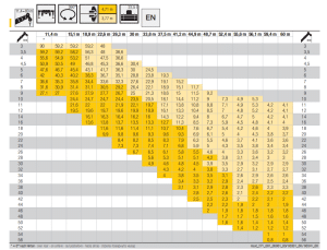
- At a 22.6m radius, with full counterweights: 47.5 tons
- At the same radius, with reduced counterweights: 36.6 tons
- That’s a 23% drop in capacity just from configuration
Counterweight Configuration vs. Lifting Capacity
| Load Radius (m) | Max Capacity (with full CW) | Max Capacity (reduced CW) |
| 11.4 | 59.2 t | 50.6 t |
| 15.9 | 56.3 t | 41.2 t |
| 22.5 | 53.0 t | 36.4 t |
| 33.0 | 47.6 t | 33.6 t |
| 38.5 | 43.6 t | 33.9 t |
| 42.1 | 30.9 t | 30.3 t |
| 44.6 | 28.6 t | 29.3 t |
| 52.2 | 23.6 t | 23.4 t |
| 55.9 | 20.2 t | 16.1 t |
| 60.0 | 25.3 t | 8.9 t |
This data reflects how critical correct counterweight configuration is for safe operation, especially at longer radii where load moment is amplified.
4 Types of Counterweight Systems
Fixed Counterweight System
Fixed counterweights are commonly used in tower cranes and consist of precast concrete or steel blocks mounted at the rear of the counter-jib. These are non-adjustable once installed and are designed to support consistent, predictable loads throughout a project. Ideal for static, long-term construction such as high-rise buildings, they typically balance loads up to 50 tons. The simplicity of this system ensures maximum reliability with minimal configuration error.
Modular Counterweight System
Widely used in mobile, all-terrain, and crawler cranes, modular systems consist of stackable steel slabs that can be added or removed based on lift requirements. These systems are fully adjustable and often used across changing job sites with different lifting profiles. They support up to 100+ tons of counterweight, making them suitable for infrastructure, civil works, and general construction. Their flexibility, ease of transport, and compatibility with load charts make them highly practical.
Hydraulic Superlift Counterweight System
The hydraulic Superlift system is found in large crawler cranes handling ultra-heavy and long-radius lifts. It uses a hydraulically extendable tray or wagon that increases the distance from the crane’s pivot, improving leverage. This system allows for real-time adjustability and is commonly used in wind turbine installation, bridge lifting, and industrial plant construction. It can accommodate 200-300+ tons of counterweight, helping maintain balance during complex or high-risk operations.
Ballast Tank (Fluid-Based) Counterweight System
Ballast tank systems are used in floating cranes or marine barge-mounted lifting platforms, especially for offshore and port operations. Instead of solid weights, they use fluid-filled tanks, usually water, that can be pumped between compartments to dynamically balance the crane in real time. These systems are continuously adjustable and support over 1,000 tons of compensating ballast, depending on vessel size. Their adaptability to wave motion and platform tilt makes them essential in maritime environments.
Impact on Structural Engineering and Ground Pressure
- Counterweight Influence: Counterweights increase total crane mass, resulting in higher ground pressure through outriggers or tracks. A 100-ton crawler crane with full counterweights can exert 250-350 kPa at each contact point.
- Ground Pressure Management: Exceeds safe bearing capacity of typical construction soil (often <150 kPa). Requires use of load-distribution systems: steel pads, timber mats, or engineered platforms.
- Soil and Site Assessment: Ground must be tested via geotechnical surveys for:
- CBR (California Bearing Ratio)
- Moisture content
- Compaction level
Governed by AS 3798 (site prep) and AS 2550.1 Clause 7.4.1 (crane setup).
- Load Spreading Techniques: Common mat sizes: 1.2m-1.5m square steel pads for mobile cranes. Cribbing is used under crawler shoes to distribute force over uneven terrain.
- Risks of Poor Ground Prep: Sinking, outrigger uplift, crane tilt or collapse, even if within rated capacity. Structural engineers must validate all base conditions prior to lift.
Cranes That Require Counterweights
Here’s a classification table of common cranes and their counterweight usage:
| Crane Type | Needs Counterweight | Placement | Why It Matters |
| Tower Crane | Yes | Rear counter-jib | Balances boom moments; essential for high-altitude stability |
| Mobile Crane | Yes | Rear of frame | Enables lifting on long booms with compact footprint |
| Crawler Crane | Yes | Rear frame + Superlift | Handles extremely heavy loads with wide track support |
| Overhead Crane | No | Not applicable | Load is supported symmetrically on bridge rails |
| Floating Crane | Yes | Ballast tanks | Maintains vessel stability amid wave motion |
| Knuckle Boom (truck-mounted) | Sometimes | Rear chassis | Needed for heavy lifting or extended articulation |
Counterweight Checklist: Crane Operation Best Practices
Before any lift involving counterweights:
- Confirm crane configuration matches load chart.
- Verify counterweight slabs are properly installed and secured.
- Check ground conditions and use appropriate mats or steel plates.
- Use only qualified personnel to configure or modify counterweights.
- Document weight and configuration in the lift plan.
- Follow AS 2550.1 and crane manufacturer’s safety guidelines.
Safety and Compliance: Risk of Misconfiguration
Misconfigured counterweights are among the top 3 causes of crane-related incidents. Risks include
- Crane tipping or collapsing under load
- Overloading the slewing ring or boom pivot
- Breach of AS 2550.1 or AS 1418.5, leading to liability
Conclusion
Counterweights are far more than just heavy attachments, they are a critical part of a crane’s structural balance and lifting capability. From placing a precast wall panel at 10 metres to installing a turbine blade at 60 metres, the right counterweight setup determines whether a lift is safe, successful, and compliant with Australian standards.
At AOR Cranes, our team specializes in tailored crane hire solutions with precisely configured counterweight systems for every job. Whether you’re managing a high-rise build in Sydney or a remote infrastructure project across NSW, we ensure your lifts are engineered for maximum safety and performance every time.
AOR Cranes is dedicated to delivering top-notch crane hire services with safety, reliability, and expertise at the core. With over 30 years of experience, we handle every project with care and expertise to meet your needs.